Deep Drawing Deformation Analysis: Stress, Strain & Optimization
Deep drawing is a fundamental metal forming process that transforms flat sheet metal blanks into seamless, hollow components by applying controlled mechanical force through specialized dies and punches. As a core technique in the stamping industry, it enables the production of high-strength, dimensionally accurate parts for automotive, aerospace, electronics, and consumer goods applications. At ChinaCustomStamping, a professional metal stamping and deep drawing manufacturer in China, we leverage decades of experience to master the nuances of deep drawing deformation, ensuring consistent quality, minimal material waste, and optimal performance for every component we produce. This comprehensive analysis explores the mechanics of deep drawing deformation, comparing cylindrical and rectangular part behavior, examining stress-strain dynamics, and outlining key considerations for process optimization and quality control.
1. Introduction to Deep Drawing and Deformation Basics
Deep drawing is defined as a metal forming operation where a flat sheet metal blank is forced through a die cavity by a punch, creating a hollow part with depth greater than or equal to its diameter. Unlike simple stamping or bending, which involve localized material manipulation, deep drawing relies on controlled plastic flow of the metal to maintain structural integrity while achieving complex three-dimensional shapes. The process is characterized by the transformation of a two-dimensional blank into a three-dimensional component, with material flowing inward from the flange region into the die cavity under the combined influence of tensile, compressive, and bending stresses.
The fundamental goal of deep drawing is to convert the blank into the desired shape without causing defects such as tearing, wrinkling, excessive thinning, or springback. These defects arise from uneven deformation, improper stress distribution, or inadequate process control, making a thorough understanding of deformation behavior critical for successful manufacturing. At ChinaCustomStamping, we begin every project with a detailed analysis of material properties, part geometry, and process parameters to predict deformation patterns and implement targeted solutions to mitigate risks.
To visualize the deformation process, engineers often use grid strain analysis, where a uniform grid pattern is etched onto the blank surface before forming. As the blank undergoes deep drawing, the grid lines distort, providing a clear picture of material flow, strain distribution, and areas of high deformation. This technique, illustrated in Figure 6-1 (from the reference text), reveals how the initially uniform grid transforms into elongated, compressed, and sheared patterns, reflecting the complex interplay of forces acting on the metal.
2. Cylindrical Part Deep Drawing: Deformation Characteristics and Stress-Strain Analysis
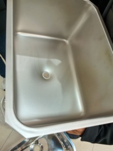
Cylindrical parts represent the most basic form of deep drawn components, and their axisymmetric geometry simplifies the analysis of deformation behavior. The process begins with a circular blank, which is gradually drawn into a cylindrical shape by a punch moving through a die cavity. The deformation of cylindrical parts is divided into five distinct zones, each with unique stress and strain characteristics, as detailed in Table 6-1 (from the reference text).
2.1 Deformation Zones in Cylindrical Deep Drawing
1. Flange Region (Main Deformation Zone)
The flange region, located between the blank holder and the die cavity, is the primary site of plastic deformation during deep drawing. As the punch descends, the material in this region is pulled radially inward toward the die opening, creating radial tensile stress (σ₁). Simultaneously, the circumferential flow of material causes tangential compressive stress (σ₃), which tends to thicken the material and can lead to wrinkling if not controlled by the blank holder force.
The grid strain analysis reveals that the initially concentric circles on the blank become straight lines in the cylindrical wall, while the radial lines become circumferential arcs. The spacing between these lines increases near the top of the cup, indicating material elongation and thinning in the axial direction. The flange region is where the majority of the forming work is done, and its behavior directly impacts the quality of the final part.
2. Die Radius Region (Transition Zone)
The die radius, where the blank transitions from the flat flange to the vertical wall, is a critical transition zone. Here, the material is subjected to both bending stress (due to the sharp curvature of the die radius) and the same radial tensile stress present in the flange. The combined effect of these stresses creates a high-strain environment, with the risk of material cracking if the die radius is too small or the drawing speed is too high. The strain at the die radius is particularly severe, as the material must undergo both plastic bending and tensile stretching simultaneously.
3. Side Wall Region (Force Transmission Zone)
Once the material passes the die radius, it enters the side wall region, which acts as a “force transmission zone.” The primary stress here is radial tensile stress, which is transmitted from the flange to the punch, pulling the material downward. The side wall experiences uniaxial tension, leading to slight thinning of the material. The extent of thinning depends on the material’s ductility, the draw ratio, and the friction between the blank and the die/punch surfaces.
4. Punch Radius Region (Transition Zone)
Similar to the die radius, the punch radius is a transition zone where the material bends around the punch tip. Here, the material is subjected to compressive stress from the punch and tensile stress from the side wall, creating a complex stress state. The punch radius is also a potential site for cracking, especially if the radius is too small or the material is prone to shear failure. The strain distribution in this region is critical, as it determines the minimum thickness of the part, which in turn affects its structural integrity.
5. Bottom Region (Small Deformation Zone)
The bottom of the cylindrical part undergoes minimal deformation compared to the other zones. The material remains relatively flat, with only slight stretching due to the punch pressure. The stress state here is predominantly biaxial tension, but the magnitude of deformation is small enough that it is often ignored in preliminary analyses. However, for parts with high draw ratios, the bottom region can experience significant thinning, requiring careful process optimization to avoid defects.
2.2 Stress and Strain Distribution in Cylindrical Parts
The stress-strain state during cylindrical deep drawing is highly dynamic, with different regions experiencing varying combinations of tensile, compressive, and bending stresses. The flange region is dominated by radial tension and tangential compression, leading to material thickening and potential wrinkling. The die and punch radii experience high bending stresses, while the side wall is primarily under uniaxial tension.
The tangential compressive stress in the flange region is a key factor in wrinkling, a common defect in deep drawing. If the blank holder force is insufficient, the material in the flange can buckle under the compressive stress, forming wrinkles that cannot be eliminated by subsequent forming operations. Conversely, excessive blank holder force increases radial tensile stress, leading to material tearing at the die radius. Balancing these two opposing effects is critical for successful deep drawing.
The strain distribution in cylindrical parts is non-uniform, with the highest strains occurring at the die radius and the lowest at the bottom of the cup. The wall thickness varies accordingly, with the thinnest section typically found near the punch radius, where the combined effects of tension and bending are most severe. This thickness variation is illustrated in Figure 6-3 (from the reference text), which shows the typical wall thickness profile of a deep drawn cylindrical part.
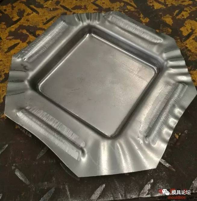
3. Rectangular Part Deep Drawing: Deformation Characteristics and Differences from Cylindrical Parts
Rectangular parts, also known as box-shaped parts, present unique challenges in deep drawing due to their non-axisymmetric geometry. Unlike cylindrical parts, where deformation is uniform around the circumference, rectangular parts experience uneven material flow, with the corners and straight edges behaving differently. This non-uniform deformation leads to complex stress and strain distributions, requiring specialized process design and tooling.
3.1 Deformation Characteristics of Rectangular Parts
To analyze the deformation of rectangular parts, engineers use grid strain analysis similar to that used for cylindrical parts. As shown in Figure 6-5 (from the reference text), the grid pattern on a rectangular blank deforms unevenly during deep drawing. The straight edges experience compression and elongation, while the corners undergo more severe deformation due to material flow from the straight sections. The key observations from the grid analysis include:
- The straight edges are compressed by the material flowing from the corners, leading to uneven strain distribution.
- The corners experience higher tensile stress than the straight edges, making them more prone to tearing.
- The height of the drawn part varies across the perimeter, with the corners being taller than the straight edges due to greater material flow.
3.2 Key Differences Between Rectangular and Cylindrical Deep Drawing
The deformation behavior of rectangular parts differs significantly from cylindrical parts, with several key distinctions:
1. Stress Distribution
In rectangular parts, the radial tensile stress (σ₁) is highest at the center of the corners and lowest at the midpoints of the straight edges. The tangential compressive stress (σ₃) is also unevenly distributed, being highest at the corners and decreasing toward the straight edges. This non-uniform stress distribution means that rectangular parts have a lower risk of wrinkling in the straight edges but a higher risk of tearing at the corners compared to cylindrical parts.
2. Material Flow
Material flow in rectangular parts is highly directional, with material from the straight edges flowing toward the corners to form the box shape. This flow pattern creates complex interactions between the straight and corner sections, with the corners “pulling” material from the edges. The extent of this interaction depends on the ratio of the corner radius (r) to the short side width (B) of the part (r/B) and the ratio of the part height (H) to the short side width (H/B).
- When r/B is small (i.e., sharp corners), the resistance to material flow at the corners increases, leading to higher tensile stress and a greater risk of tearing.
- When H/B is large (i.e., deep boxes), the material flow from the straight edges to the corners is more pronounced, increasing the deformation at the corners and the risk of cracking.
3. Formability Limits
Rectangular parts generally have lower formability limits than cylindrical parts due to the uneven stress distribution. The draw ratio for rectangular parts is typically lower than that for cylindrical parts, as the corners cannot withstand the same level of tensile stress. To improve formability, engineers often use larger corner radii, multiple drawing operations, or intermediate annealing to relieve stresses.
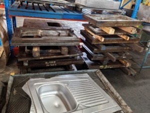
4. Trimming Allowance Selection: Ensuring Part Quality in Deep Drawing
Deep drawn parts rarely meet the required dimensional tolerances immediately after forming. Due to material springback, uneven deformation, and minor dimensional variations, most parts require a trimming operation to remove excess material and achieve the final dimensions. The trimming allowance, or the amount of extra material left on the part after drawing, is a critical parameter that balances material waste with the need for a clean, accurate cut.
4.1 Trimming Allowance for Cylindrical Parts
The trimming allowance for cylindrical parts depends on the part height, relative height (h/d, where h is the part height and d is the diameter), and material properties. Table 6-2 (from the reference text) provides standard trimming allowances for cylindrical parts, with values ranging from 1.0 mm for short parts (h/d < 0.8) to 12 mm for tall parts (h/d > 2.5~4). The allowance increases with part height because taller parts experience more uneven deformation, requiring more material to be removed during trimming.
For parts with low dimensional requirements, the trimming allowance can be reduced or eliminated entirely, but this increases the risk of dimensional errors and surface defects. At ChinaCustomStamping, we carefully calculate trimming allowances based on the specific part geometry and tolerance requirements, ensuring that our customers receive parts that meet their exact specifications without unnecessary material waste.
4.2 Trimming Allowance for Flanged Cylindrical Parts
Flanged cylindrical parts, which have a rim or flange around the top edge, require additional consideration for trimming allowance. The allowance depends on the flange diameter (dₐ) and the relative flange diameter (dₐ/d), as shown in Table 6-3 (from the reference text). For example, parts with small flanges (dₐ/d < 1.5) require a trimming allowance of 1.6 to 6 mm, while parts with larger flanges (dₐ/d > 2.5~3) require 1.0 to 3.0 mm. The allowance is determined by the degree of flange deformation, with larger flanges experiencing more uneven material flow and requiring more trimming.
5. Factors Influencing Deep Drawing Deformation and Formability
The success of a deep drawing operation depends on a complex interplay of material properties, part geometry, and process parameters. Understanding these factors is essential for optimizing deformation behavior and producing high-quality parts.
5.1 Material Properties
The ductility, yield strength, and strain hardening behavior of the material are the most significant factors affecting deep drawing formability. Materials with high ductility (e.g., aluminum alloys, low-carbon steel) can withstand greater deformation without tearing, while materials with high yield strength (e.g., stainless steel) require higher forming forces and are more prone to springback. Strain hardening, which increases the material’s strength as it is deformed, can both help and hinder the process: it strengthens the material in high-strain regions but can also lead to localized thinning and cracking if not controlled.
At ChinaCustomStamping, we work with a wide range of materials, including steel, stainless steel, aluminum, copper, and brass, and we tailor our process parameters to each material’s unique properties. For example, we use higher blank holder forces for materials prone to wrinkling and slower drawing speeds for brittle materials to minimize the risk of cracking.
5.2 Part Geometry
The geometry of the part, including its shape, depth, corner radii, and wall thickness, has a profound impact on deformation behavior. Key geometric factors include:
- Draw Ratio: The ratio of the blank diameter to the part diameter (for cylindrical parts) or the ratio of the part height to its width (for rectangular parts). Higher draw ratios mean greater deformation and a higher risk of defects.
- Corner Radii: Sharp corners increase stress concentrations and material flow resistance, leading to higher tensile stress and a greater risk of tearing.
- Wall Thickness: Thicker materials are more resistant to wrinkling but require higher forming forces and are more prone to cracking at sharp radii.
5.3 Process Parameters
Process parameters such as blank holder force, drawing speed, lubrication, and die/punch geometry play a critical role in controlling deformation.
- Blank Holder Force: As discussed earlier, the blank holder force must be balanced to prevent both wrinkling (too low) and tearing (too high).
- Drawing Speed: Higher drawing speeds can increase production rates but may lead to higher strain rates, which can reduce material ductility and increase the risk of cracking.
- Lubrication: Proper lubrication reduces friction between the blank and the die/punch surfaces, improving material flow and reducing the risk of localized thinning and tearing.
- Die/Punch Geometry: The radius of the die and punch, the clearance between them, and the surface finish all affect stress distribution and material flow.
6. Quality Control and Defect Mitigation in Deep Drawing
Despite careful process design, deep drawing operations can still experience defects such as wrinkling, tearing, excessive thinning, springback, and dimensional inaccuracies. At ChinaCustomStamping, we implement a comprehensive quality control program to identify and mitigate these defects, ensuring that every part meets our customers’ specifications.
6.1 Common Defects and Their Causes

- Wrinkling: Caused by insufficient blank holder force, excessive tangential compressive stress, or material with low resistance to buckling.
- Tearing: Occurs when the radial tensile stress exceeds the material’s ultimate tensile strength, typically at the die or punch radii. Causes include excessive blank holder force, sharp radii, high draw ratios, or material with low ductility.
- Excessive Thinning: Caused by uneven material flow, high tensile stress, or inadequate lubrication. The thinnest section of the part is often found near the punch radius.
- Springback: The tendency of the material to return to its original shape after forming, leading to dimensional inaccuracies. More common in materials with high yield strength and parts with complex geometries.
- Surface Defects: Including scratches, die marks, and galling, caused by poor lubrication, improper die/punch surface finish, or material contamination.
6.2 Mitigation Strategies
To address these defects, we employ a range of strategies, including:
- Process Optimization: Adjusting blank holder force, drawing speed, and lubrication to balance material flow and stress distribution.
- Tooling Design: Using larger die/punch radii, polished surfaces, and optimized clearances to reduce stress concentrations and improve material flow.
- Material Selection: Choosing materials with appropriate ductility and strain hardening behavior for the application.
- Multiple Drawing Operations: For high draw ratio parts, using sequential drawing operations with intermediate annealing to relieve stresses and improve formability.
- Post-Forming Operations: Trimming, annealing, and surface finishing to remove excess material, relieve stresses, and improve dimensional accuracy.
7. Conclusion: Mastering Deep Drawing Deformation for Precision Manufacturing
Deep drawing is a complex and versatile metal forming process that requires a deep understanding of material behavior, stress-strain dynamics, and process control. By analyzing the deformation characteristics of cylindrical and rectangular parts, identifying the key factors influencing formability, and implementing targeted process optimization strategies, manufacturers can produce high-quality, defect-free deep drawn components.
At ChinaCustomStamping, we bring decades of expertise in metal stamping and deep drawing to every project, leveraging advanced process design, precision tooling, and rigorous quality control to meet the most demanding customer requirements. Whether producing simple cylindrical cups or complex rectangular enclosures, our team of engineers and technicians work closely with customers to understand their needs, optimize the process, and deliver parts that exceed expectations. By mastering the intricacies of deep drawing deformation, we ensure that our customers receive components that are not only dimensionally accurate but also structurally sound and cost-effective.
As the demand for lightweight, high-strength components continues to grow in industries such as automotive, aerospace, and electronics, the importance of deep drawing as a manufacturing process will only increase. By staying at the forefront of process innovation and material science, ChinaCustomStamping is well-positioned to meet the evolving needs of our customers, delivering innovative solutions that drive success in the global marketplace.

